- 您现在的位置:买卖IC网 > Sheet目录2001 > ISL12023IVZ (Intersil)IC RTC/CLDR TEMP SNSR 14-TSSOP
ISL12023
3
FN6682.3
December 6, 2011
Absolute Maximum Ratings
Thermal Information
Voltage on VDD, VBAT and IRQ/FOUT pins
(respect to ground) . . . . . . . . . . . . . . . . . . . . . . . . . . . . . . . . . -0.3V to 6.0V
Voltage on SCL and SDA pins
(respect to ground) . . . . . . . . . . . . . . . . . . . . . . . . . . . . -0.3V to VDD +0.3V
Voltage on X1 and X2 pins
(respect to ground) . . . . . . . . . . . . . . . . . . . . . . . . . . . . . . . . . -0.3V to 2.5V
ESD Rating
Human Body Model (Per MIL-STD-883 Method 3014) . . . . . . . . . . >3kV
Machine Model . . . . . . . . . . . . . . . . . . . . . . . . . . . . . . . . . . . . . . . . . . >300V
Thermal Resistance (Typical, Note 3)
θJA (°C/W)
14 Ld TSSOP . . . . . . . . . . . . . . . . . . . . . . . . . . . . . . . . . . .
100
Storage Temperature . . . . . . . . . . . . . . . . . . . . . . . . . . . . . .-65°C to +150°C
Pb-free Reflow Profile . . . . . . . . . . . . . . . . . . . . . . . . . . . . . . . see link below
CAUTION: Do not operate at or near the maximum ratings listed for extended periods of time. Exposure to such conditions may adversely impact product
reliability and result in failures not covered by warranty.
NOTE:
3.
θJA is measured with the component mounted on a high effective thermal conductivity test board in free air. See Tech Brief TB379 for details.
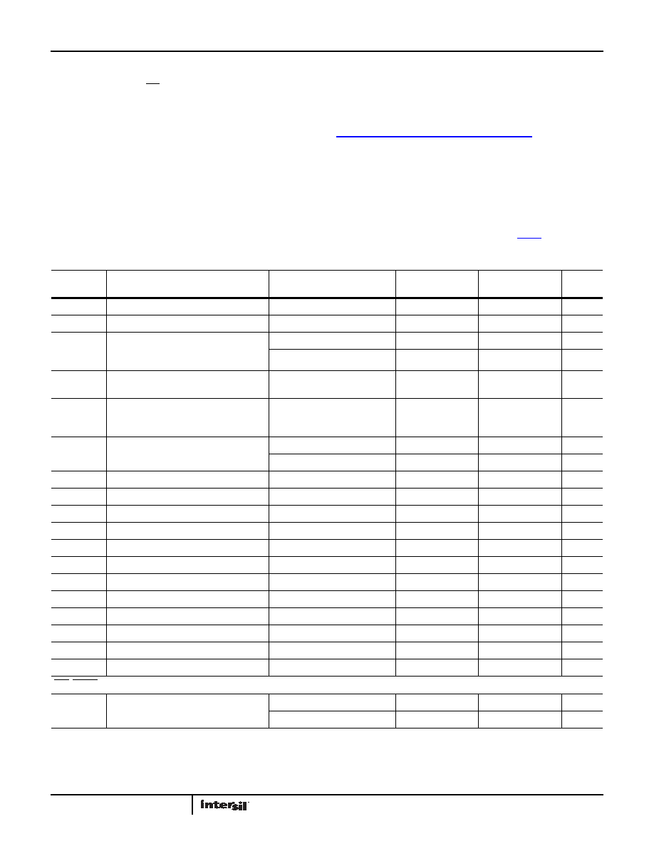
DC Operating Characteristics - RTC Test Conditions: VDD = +2.7V to +5.5V, TA = -40°C to +85°C, unless otherwise stated.
SYMBOL
PARAMETER
CONDITIONS
MIN
(Note 11)
TYP
(Note 7)
MAX
(Note 11)
UNITS
NOTES
VDD
Main Power Supply
(Note 13)
2.7
5.5
V
VBAT
Battery Supply Voltage
(Note 13)
1.8
5.5
V
IDD1
Supply Current. (I2Cnot Active,
Temperature Conversion not Active, FOUT
not Active)
VDD = 5V
4.1
15
A
VDD = 3V
3.5
14
A
IDD2
Supply Current. (I2C Active, Temperature
Conversion not Active, FOUT not Active)
VDD = 5V
200
500
A
IDD3
Supply Current. (I2Cnot Active,
Temperature Conversion Active, FOUT not
Active)
VDD = 5V
120
400
A
IBAT
Battery Supply Current
VDD = 0V, VBAT = 3V, TA = +25°C
1.0
1.6
A
VBAT = 3V
1.0
5.0
A
IBATLKG
Battery Input Leakage
VDD = 5.5V, VBAT = 1.8V
100
nA
ILI
Input Leakage Current on SCL
-1.0
±0.1
1.0
A
ILO
I/O Leakage Current on SDA
-1.0
±0.1
1.0
A
VBATM
Battery Level Monitor Threshold
-100
+100
mV
VPBM
Brownout Level Monitor Threshold
-100
+100
mV
VTRIP
VBAT Mode Threshold
(Note 13)
2.0
2.2
2.4
V
VTRIPHYS
VTRIP Hysteresis
30
mV
VBATHYS
VBAT Hysteresis
50
mV
ΔFoutT
Frequency Stability vs Temperature
2.7V
≤ VDD ≤ 3.6V,
-5
+5
ppm
ΔFoutV
Frequency Stability vs Voltage
2.7V
≤ VDD ≤ 3.6V
-3
+3
ppm
ΔATLSB
AT Sensitivity per LSB
BETA (3:0) = 1000
0.5
1
2
ppm
Temp
Temperature Sensor Accuracy
VDD = VBAT = 3.3 V
±2
°C
IRQ, LVRST, FOUT
VOL
Output Low Voltage
VDD = 5V, IOL = 3mA
0.4
V
VDD = 2.7V, IOL = 1mA
0.4
V
发布紧急采购,3分钟左右您将得到回复。
相关PDF资料
ISL12024IRTCZ
IC RTC/CALENDER 64BIT 8-TDFN
ISL12024IVZ
IC RTC/CALENDAR EEPROM 8-TSSOP
ISL12025IVZ
IC RTC/CALENDAR EEPROM 8-TSSOP
ISL12026IBZ-T7A
IC RTC/CALENDAR EEPROM 8SOIC
ISL12027IV27AZ
IC RTC/CALENDAR EEPROM 8-TSSOP
ISL12028IVZ
IC RTC/CALENDAR EEPROM 14-TSSOP
ISL12029IVZ
IC RTC/CALENDAR EEPROM 14-TSSOP
ISL12030IBZ
IC RTC/CALENDAR EEPROM 8-SOIC
相关代理商/技术参数
ISL12023IVZ-T
功能描述:实时时钟 REAL TIME CLK/CLNDR W/TEMP COM 14 L RoHS:否 制造商:Microchip Technology 功能:Clock, Calendar. Alarm RTC 总线接口:I2C 日期格式:DW:DM:M:Y 时间格式:HH:MM:SS RTC 存储容量:64 B 电源电压-最大:5.5 V 电源电压-最小:1.8 V 最大工作温度:+ 85 C 最小工作温度: 安装风格:Through Hole 封装 / 箱体:PDIP-8 封装:Tube
ISL12024
制造商:INTERSIL 制造商全称:Intersil Corporation 功能描述:Real-Time Clock/Calendar with Embedded Unique ID
ISL12024IBZ
功能描述:实时时钟 REAL TIME CLK/CLNDR W/EEPROM IN 8LD RoHS:否 制造商:Microchip Technology 功能:Clock, Calendar. Alarm RTC 总线接口:I2C 日期格式:DW:DM:M:Y 时间格式:HH:MM:SS RTC 存储容量:64 B 电源电压-最大:5.5 V 电源电压-最小:1.8 V 最大工作温度:+ 85 C 最小工作温度: 安装风格:Through Hole 封装 / 箱体:PDIP-8 封装:Tube
ISL12024IBZ-T
功能描述:实时时钟 REAL TIME CLK/CLNDR W/EEPROM IN 8LD RoHS:否 制造商:Microchip Technology 功能:Clock, Calendar. Alarm RTC 总线接口:I2C 日期格式:DW:DM:M:Y 时间格式:HH:MM:SS RTC 存储容量:64 B 电源电压-最大:5.5 V 电源电压-最小:1.8 V 最大工作温度:+ 85 C 最小工作温度: 安装风格:Through Hole 封装 / 箱体:PDIP-8 封装:Tube
ISL12024IRTCZ
功能描述:实时时钟 RTC OUTPUT PROGRAM TO 32KHZ W/EEPROM 8 RoHS:否 制造商:Microchip Technology 功能:Clock, Calendar. Alarm RTC 总线接口:I2C 日期格式:DW:DM:M:Y 时间格式:HH:MM:SS RTC 存储容量:64 B 电源电压-最大:5.5 V 电源电压-最小:1.8 V 最大工作温度:+ 85 C 最小工作温度: 安装风格:Through Hole 封装 / 箱体:PDIP-8 封装:Tube
ISL12024IRTCZ-T
功能描述:实时时钟 RTC OUTPUT PROGRAM TO 32KHZ W/EEPROM 8 RoHS:否 制造商:Microchip Technology 功能:Clock, Calendar. Alarm RTC 总线接口:I2C 日期格式:DW:DM:M:Y 时间格式:HH:MM:SS RTC 存储容量:64 B 电源电压-最大:5.5 V 电源电压-最小:1.8 V 最大工作温度:+ 85 C 最小工作温度: 安装风格:Through Hole 封装 / 箱体:PDIP-8 封装:Tube
ISL12024IVZ
功能描述:实时时钟 REAL TIME CLK/CLNDR W/EEPROM IN 8LD RoHS:否 制造商:Microchip Technology 功能:Clock, Calendar. Alarm RTC 总线接口:I2C 日期格式:DW:DM:M:Y 时间格式:HH:MM:SS RTC 存储容量:64 B 电源电压-最大:5.5 V 电源电压-最小:1.8 V 最大工作温度:+ 85 C 最小工作温度: 安装风格:Through Hole 封装 / 箱体:PDIP-8 封装:Tube
ISL12024IVZ-T
功能描述:实时时钟 REAL TIME CLK/CLNDR W/EEPROM IN 8LD RoHS:否 制造商:Microchip Technology 功能:Clock, Calendar. Alarm RTC 总线接口:I2C 日期格式:DW:DM:M:Y 时间格式:HH:MM:SS RTC 存储容量:64 B 电源电压-最大:5.5 V 电源电压-最小:1.8 V 最大工作温度:+ 85 C 最小工作温度: 安装风格:Through Hole 封装 / 箱体:PDIP-8 封装:Tube